DIY Vantec modification
Introduction
This page describes a particular behaviour of certain Vantec
speed controllers and one way to change that behaviour. Note that no guarantee
is given for this procedure. You should not attempt to modify any speed
controller unless you are thoroughly competent with soldering small electronic components. If
you have to return your Vantec to the manufacturer, and this modification is
present, you will probably be charged for rectification work. This modification
has been performed on several Vantecs (more than one model) and so far has
worked fine, but it is not condoned by Vantec and there is no guarantee that it will work on yours, or will not
change some other property of the controller. You're on your own!
If you are not experiencing the behaviour described below, it is recommended
that you do not make any changes to your controller. If it isn't broken...
Description
It has been noticed by several people that when certain Vantecs (it has been
observed on several different models of Vantecs) are used in certain situations,
there is the possibility of the Vantec resetting itself under high-load
conditions. Alan Gribble, creator of the great Pussycat, observed this behaviour
on one of his Vantecs a couple of years ago and set about finding a 'fix'. After
some considerable research, he developed the procedure described below. Many
thanks to Alan for allowing the procedure to be publicised.
We observed it when running our RDFR47E at 36 Volts (three sets of 3Ah
NiCads) driving a pair of Bosch GPA 750 motors. In retrospect, it was also what
caused KHz mobility problems in BattleBots Season 4 against Little Sister and
Surgeon General. Whenever a full power start was
attempted, the Vantec would reset, which would cause the motors to loose all
power for about one second. After the one second, the controller would recover
fully.
If driven around 'softly', there would be no problem. The behaviour was
also noticed when running at 24 Volts, but less so. Once the 24V batteries had
been discharged to around half capacity, the controller usually behaved fine, so
it seems to be related to the amount of load that the controller is having to
handle - light loads and everything is OK (you will not be able to reproduce it
with the machines wheels in the air), but over a certain limit, the behaviour
starts appearing.
We attempted other solutions, like fitting a large capacitor to the input
lines on the Vantec and several ferrite sleeves to the motor leads, but with no noticeable
effect.
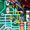
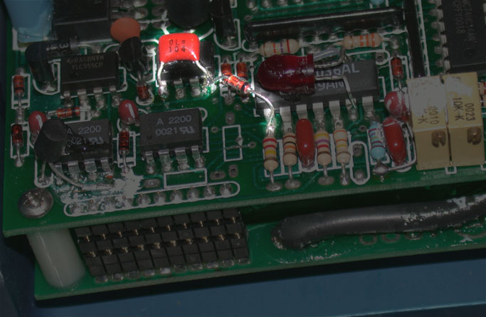
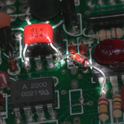 There
was thought to be a factory 'fix' for this behaviour. On Vantecs purchased since
the middle of 2001, maybe earlier, it has been noticed that a capacitor and
diode had been added to the circuit board, highlighted on the picture on the
left. Click on the picture for a larger view. However although our Vantec RDFR47E, purchased in late 2001, had this
'fix', it still exhibited the behaviour.
There
was thought to be a factory 'fix' for this behaviour. On Vantecs purchased since
the middle of 2001, maybe earlier, it has been noticed that a capacitor and
diode had been added to the circuit board, highlighted on the picture on the
left. Click on the picture for a larger view. However although our Vantec RDFR47E, purchased in late 2001, had this
'fix', it still exhibited the behaviour.
Altering the behaviour
The procedure involves soldering two new components
onto the control board of the Vantec. The controller should not need to be disassembled.
The components are:
60 Volt, 5 µF electrolytic capacitor e.g. RS
partno 324-5335
10 K Ohm resistor
It is also recommended that you attach an AC Varistor/Transient Voltage
Suppressor across each of your motors. e.g. RS partno 354-5180, manufacturers
partno P6KE47CA. This
cuts down on voltage spikes generated by the motors getting into the controller.
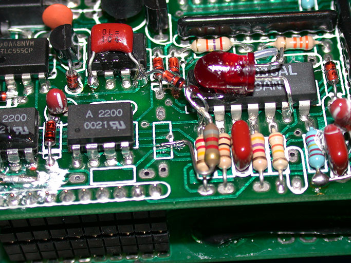
 The positive end of the cap and one end of the
resistor are both soldered onto pin one of the 14 pin DIL chip on the right of
the picture. The negative end of the cap is soldered into an unused solder pad on
the board and the other end of the resistor is soldered onto a nearby
track.
The positive end of the cap and one end of the
resistor are both soldered onto pin one of the 14 pin DIL chip on the right of
the picture. The negative end of the cap is soldered into an unused solder pad on
the board and the other end of the resistor is soldered onto a nearby
track.
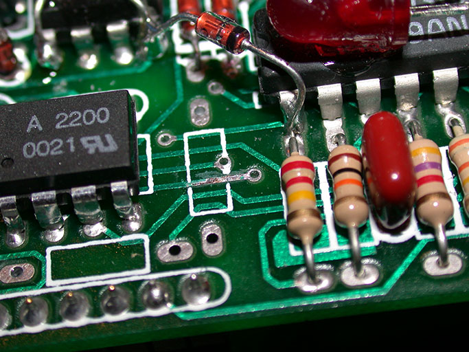
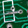 To
solder the resistor to the track, take a sharp knife and carefully scrape off
the green varnish, exposing a few mm of bare track. The exposed track, and the
solder pad for the cap are circled in the picture. Be very careful not to
damage the track itself. You may need to use a magnifying glass - those tracks
are small!
To
solder the resistor to the track, take a sharp knife and carefully scrape off
the green varnish, exposing a few mm of bare track. The exposed track, and the
solder pad for the cap are circled in the picture. Be very careful not to
damage the track itself. You may need to use a magnifying glass - those tracks
are small!
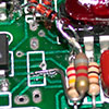 You can now solder the resistor in place. One
end is soldered onto pin one of the chip, although in this case, the controller
had the factory 'fix', so it was easier to solder onto the leg on the diode that
is also attached to pin one.
You can now solder the resistor in place. One
end is soldered onto pin one of the chip, although in this case, the controller
had the factory 'fix', so it was easier to solder onto the leg on the diode that
is also attached to pin one.
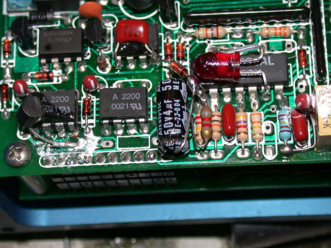
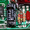 The capacitor can now be soldered in place.
The negative wire should be passed through the solder pad hole. Be careful to
crop the wire before soldering so that it does not protrude too far from the
other side of the board. It may not go all the way through the hole - ours was
blocked by glue on the other side. The positive wire is also attached to pin one of the
chip.
The capacitor can now be soldered in place.
The negative wire should be passed through the solder pad hole. Be careful to
crop the wire before soldering so that it does not protrude too far from the
other side of the board. It may not go all the way through the hole - ours was
blocked by glue on the other side. The positive wire is also attached to pin one of the
chip.
Once you are happy all is secure, put a
blob of contact adhesive or cyano on the components to keep them in place. Done!
That's all you have to do. Go and test it and keep your fingers crossed.
 There
was thought to be a factory 'fix' for this behaviour. On Vantecs purchased since
the middle of 2001, maybe earlier, it has been noticed that a capacitor and
diode had been added to the circuit board, highlighted on the picture on the
left. Click on the picture for a larger view. However although our Vantec RDFR47E, purchased in late 2001, had this
'fix', it still exhibited the behaviour.
There
was thought to be a factory 'fix' for this behaviour. On Vantecs purchased since
the middle of 2001, maybe earlier, it has been noticed that a capacitor and
diode had been added to the circuit board, highlighted on the picture on the
left. Click on the picture for a larger view. However although our Vantec RDFR47E, purchased in late 2001, had this
'fix', it still exhibited the behaviour.